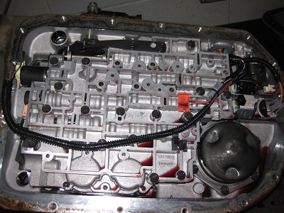
After working with all kinds of vehicles for a number of years, I decided it was time to put together my own hot-rod. I picked the Jaguar XJ6 Chevy V8 swap for a couple reasons. Early/mid 80's Jaguar XJ6's had the sweet styling and solid design of a luxury sport sedan, but lacked reliability around the engine and electrical system. As a result, they are easy to come by and relatively inexpensive. I picked the Chevrolet LS1 V8 because of it's awesome output numbers, availability, reliability and personal testimony from a couple of my friends who have them. I knew it would be a little more challenging than swapping in an LT1 or earlier engine, but so what! The outcome will be that much better.
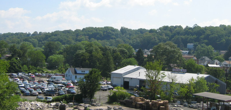
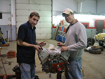
Here's where it all happens! Yurechko Auto is my parents' automotive business located outside of Pittsburgh in Boston, PA. We do a variety of things including towing for the City of Pittsburgh, used parts sales, scrap processing, body work and late model vehicle sales. This is where I worked and learned everything I know about cars today!
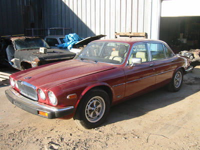
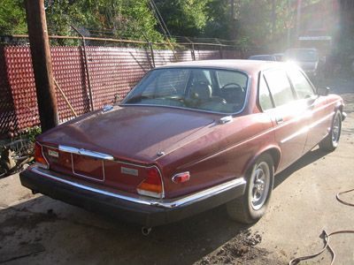
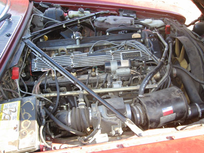
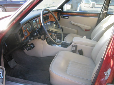
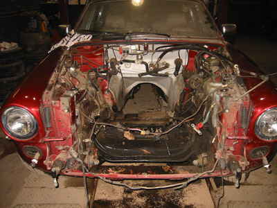
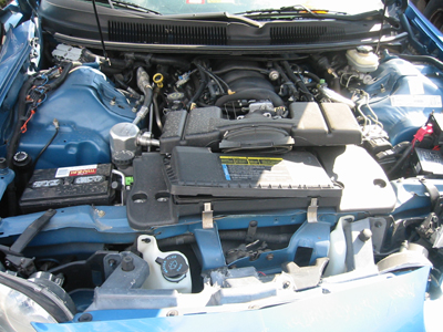
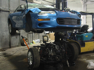
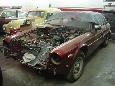
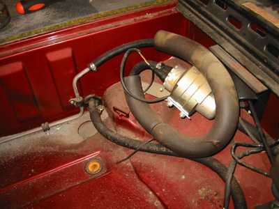
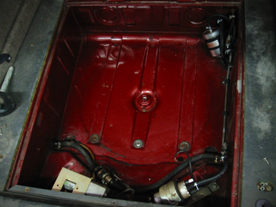
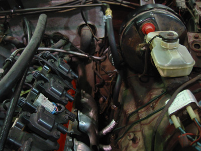
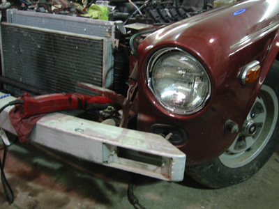
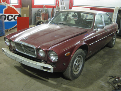
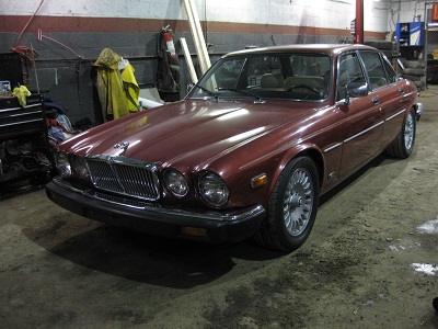
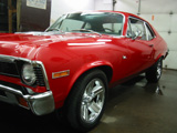
October 6th, 2004 - Here are a few shots of the car before we started working on it. We bought it off of eBay from a very nice couple in Tennessee who had to sell it in the wake of passed family member. The car has 68,000 miles and maintenance records to prove it. It is VERY VERY clean. At the time of the purchase, the engine was beyond any reasonable repair. A spark plug broke off and fell into the combustion chamber.
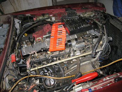
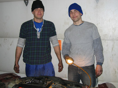
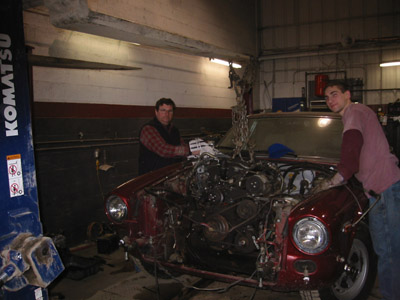
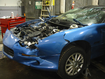
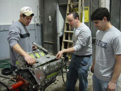
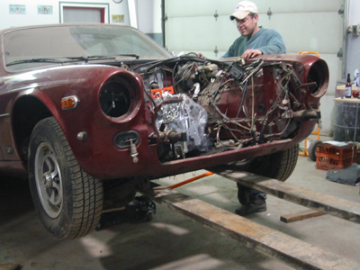
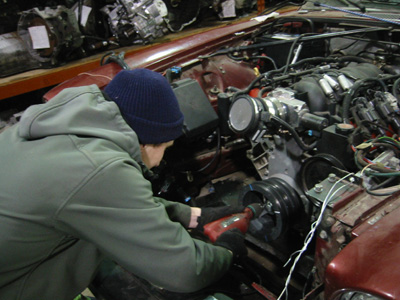
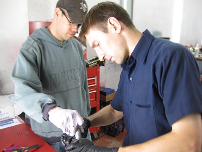
January 30th, 2005 - Today, my friend Drew and I removed most of the engine components so we could pull the engine. Not a problem!! First the hood (or "bonnet" if you prefer the British term) had to come off. That gave us easy access to everything we needed. There were very few rusty screws and bolts giving us trouble, as everything under the hood was very rust-free. This is partly because it looked like the engine had it's share of little oil leaks, which coated most of the engine bay with motor oil.
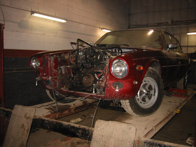
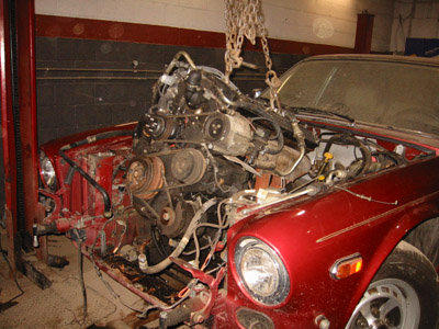
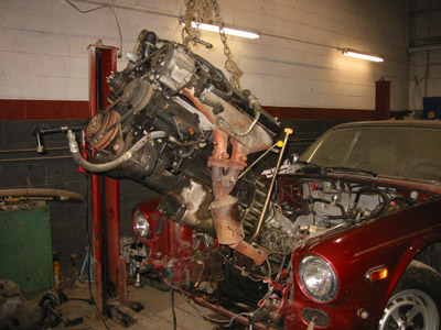
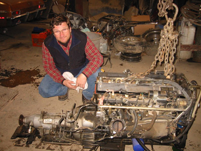
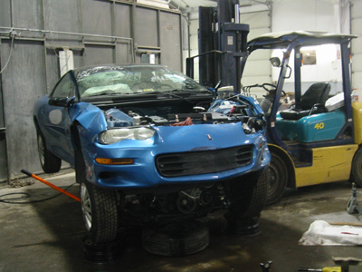
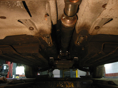
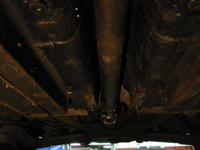
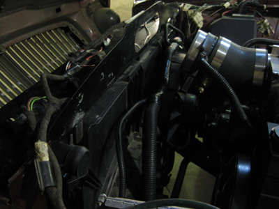
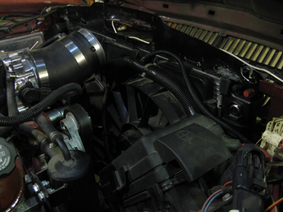
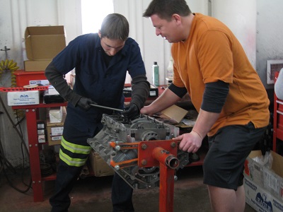
February 11th-12th, 2005 - Finally, the engine is coming out! First I removed the upper core support, radiator, condensor and oil cooler. Next I pulled the bumper and disconnected the last of the engine components. After that, I had to get under the car to remove the exhaust, transmission crossmember and disconnect the drive shaft. Once again, everything went very smoothly! Finally, my dad (Slick Mick) came over and helped me pull the engine. Of course it's always good to have his input. Just about everything I'll do during this conversion, he's probably done a couple hundred times more than me... so he always spots the big problems before I run into them!
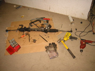
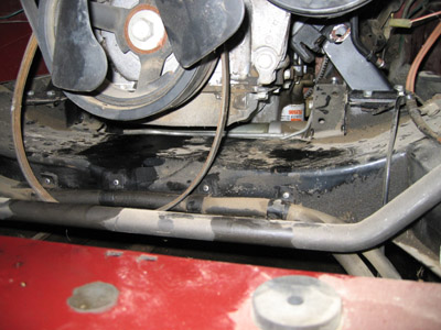
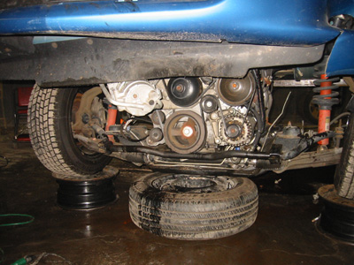
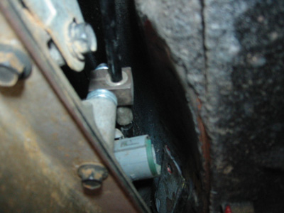
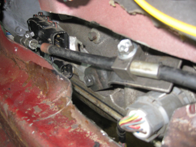
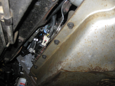
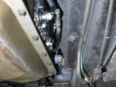
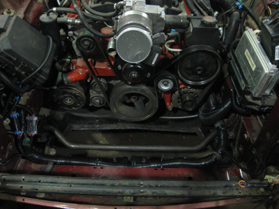
March 12th-13th, 2005 - This weekend I had big plans! I wanted to overhaul the whole front suspension but I ran out of time. I replaced the OEM steering rack bushings with urathane ones to clean up the steering response and eliminate any wandering the worn rubber bushings would allow. I had to drop the steering rack because the steel liners on the rubber bushings were seized in the rack. I also cleaned! I degreased the engine compartment a couple of times and scrubbed with hot soapy water. It came a long way but still needs more cleaning. I also removed some of the Lucas electronic engine components I wouldn't be needing.
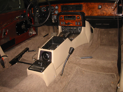
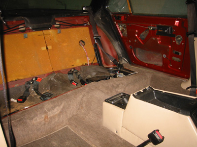
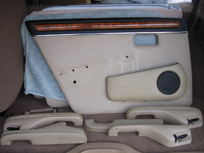
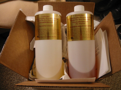
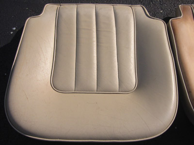
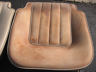
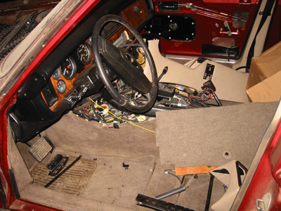
June 10th & 17th, 2005 - I ran out of mechanical work to do to the car so I decided to turn my attention to the interior. I pulled out everything that had leather on it except the steering wheel. This included the front and rear seats, center console, armrests and door map pockets. I bought a product called Leatherique (developed to restor Rolls-Royces) to treat all of the leather with. It's a two-part process: 1) massage the Rejuvinator Oil onto the leather - this is absorbed into the pores, pushing out the dirt, sweat, polution, etc while strengthening and softening the leather. 2) scrub with Pristine Clean - this cleanses the dirt brought to the surface by the oil, and works better than the stuff you see on late-night TV infomercials!! Leather is skin and the oils that keep it soft and supple dry out over time... as it may take years to dry up, it takes some time for the oils to soften the leather as well. This will take some patience on my part but so far it's working pretty good!
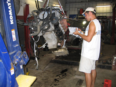
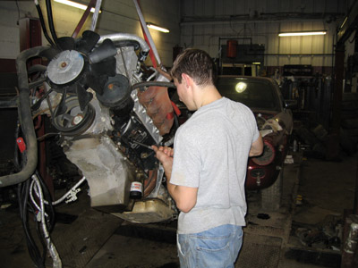
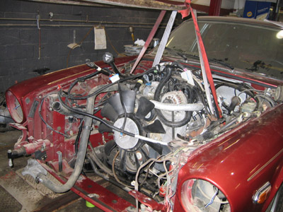
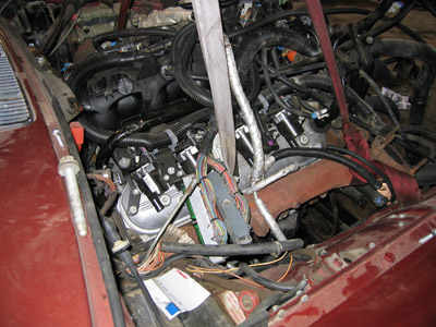
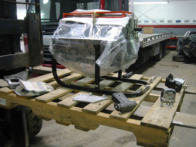
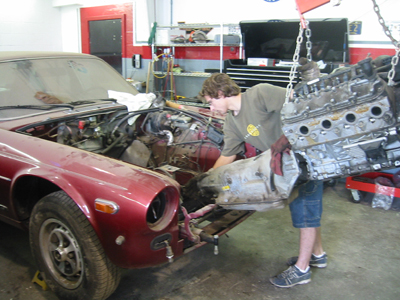
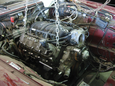
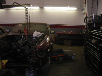
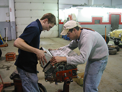
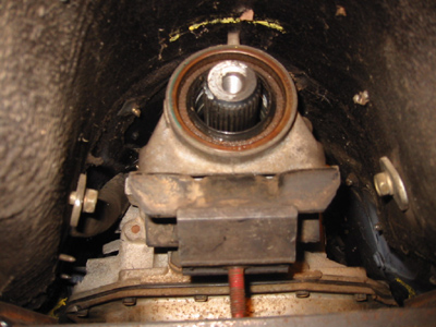
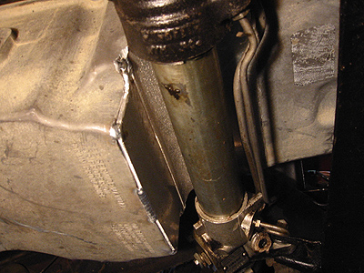
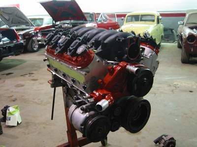
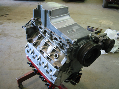
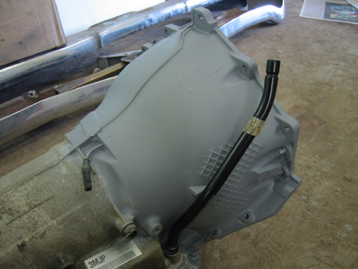
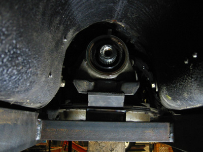
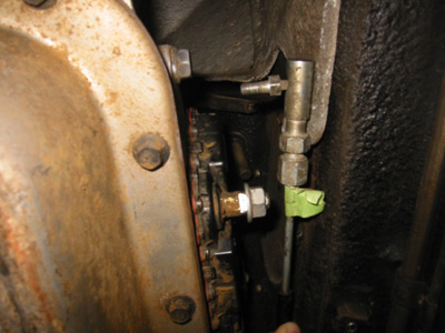
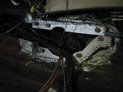
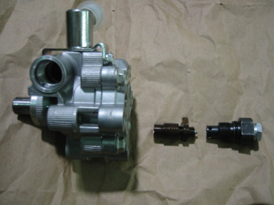
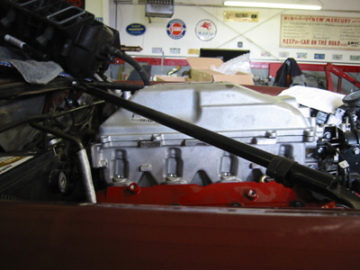
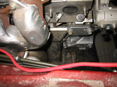
Augutst 19th, 2005 - Today we did a trial fit of the engine and trans. The engine is a 6.0L LQ4 LS1-type V8 and the transmission is a 4L80E 4-speed automatic all out of a 2003 2500 Series Chevy van. First we installed a set of Suncoast engine mount pedestals on the Jaguar chasis from Andrew at Jaguar Specialties. These pedestals relocate the Jaguar mounting points to accomodate a regular Chevy smallblock. Next, we installed a set of aluminum engine mount adapter plates from Street and Performance on the block of the engine. These moved the engine mounting points forward about three inches, changed the bolt pattern, and allowed us to use off the shelf rubber engine mounts. The LQ4 has a higher than usual nylon intake manifold and low deep sump oil pan. This combination made it VERY tough to slide the engine and trans into the engine bay. As it turns out, the oil pan sat on the steering rack and would not let us bolt the engine in... however as you can see from the pictures, we were VERY close! We pulled the engine back out and will need to find a different oil pan.
September 24th, 2005 - About all of the leather out of the vehicle has been stripped of the old laquer finish and reoiled. It took me all summer! To strip the laquer off, I used a fine grit sandpaper wet with a mixture of rubbing alcohol and amonia. The sandpaper acts as an abrasive while the alcohol and amonia mixture break down the colorant. The mixture dries very quickly, so very short burts of sanding are followed by mopping up the loose wet laquer with a large bath towel. This is very messy and very time consuming. After the laquer is stripped, the leather dries and is massaged with Leatherique Rejuvinator Oil to bring back the soft leather feel. The end product is a smooth and strong natural leather hide ready for a new colorant. It was worth every minute!
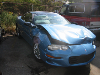
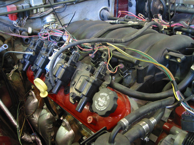
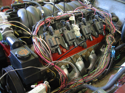
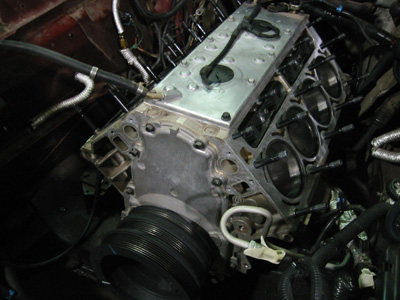
October 23rd, 2005 - Finally, I have the engine! The engine is an LS1 V8 out of a wrecked 1999 Camaro Z28. I fired it up and it runs great! The engine is rated at 305hp and 335ft/lb of torque. It features an aluminum block and heads, coil-on-plug ignition, nylon intake manifold, advanced engine management computer as well as some other features lacked by it's predecessor the LT1. The LS1 was also used in the Corvette through 2005. Although it has plenty of power to pull around my 4,000lb Jaguar, I can't resist the urge to beef it up with some aftermarket goodies!
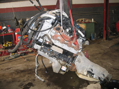
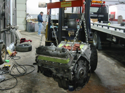
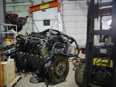
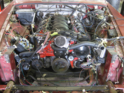
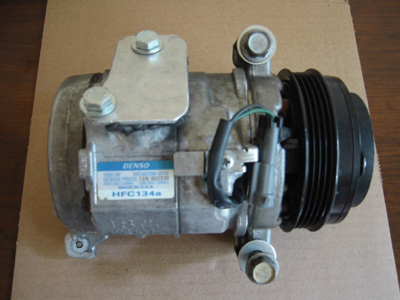
December 22nd, 2005 - Today we pulled the engine from the Z28. Since the engine is packed so tightly under the hood, the best way to pull the engine is to lift the car body off of the engine and transmission. After a few hours of work the wiring, sensors, exhaust, torque arm, driveshaft, brake lines and other things were all either disconnected or cut. The A/C compressor was removed from the engine, so the entire system went undisturbed. This keeps the A/C system sealed and will keep the components in good condition. The car body easily lifted off of the engine, trans and front suspension. I am REALLY glad I don't have to put the engine back in the Z28 - there's not much room in there!
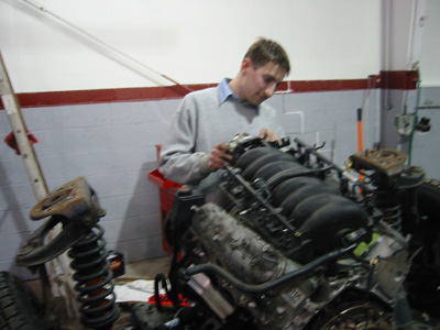
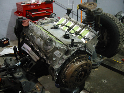
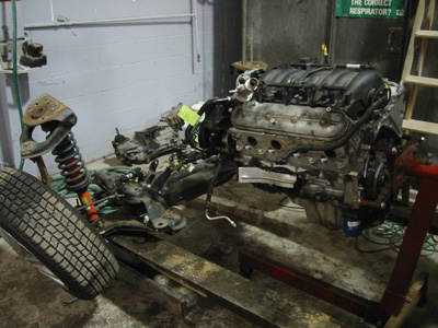
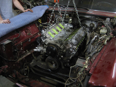
December 23rd, 2005 - After removing the engine from the car, we seperated the transmission from the engine and picked the engine and crossmember up with the forklift. We then removed the wiring harness, exhaust manifolds and a few other things we were eager to get out of the way. The engine was then put on a stand and was seperated from the remaining suspension parts. We finished stripping off the remaining accessories and drained the oil and coolant from the block. Next, the engine mount adapter plates were installed and the engine was hoisted into the Jaguar. As we suspected, the oil pan once again prevented us from seating the engine onto the engine mounts. However, it was good to see that there is plenty of room in the Jaguar for the new engine!
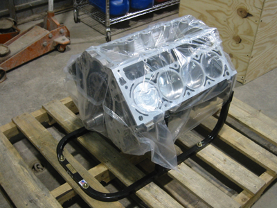
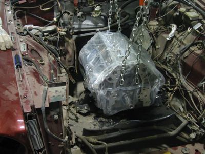
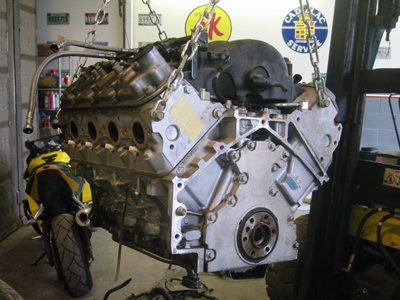
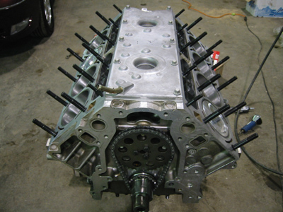
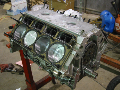
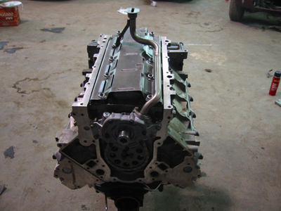
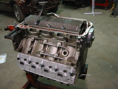
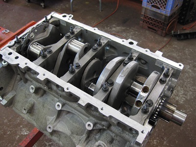
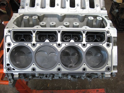
March 4th, 2006 - I decided not to use the Camaro engine, so I ordered a low-compression shortblock from Horsepower Engineering in Houston, TX. The engine is a 346ci aluminum block LS1 with a new stock cast iron crank, forged Scat I-beam rods, forged Diamond pistons, Mahle rings, Federal Mogul bearings, a stock 1999 Camaro cam and new timing gears with an LS2 chain. It was assembled with ARP main studs and rod bolts. The block was deburred, decked and honed with torque plates to simulate the heads being bolted down. The crank was recentered and the entire assembly was balanced. With the engine still in the plastic bag (to keep out harmful dirt and debris) we bolted up the motor mounts and carefully mounted the engine into the Jag. Next we slid the transmission under the car and mated it to the engine. Unfortunately, we will have to cut out a few brackets in the trans tunnel before we can level out the transmission.
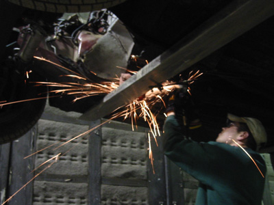
March 11th, 2006 - Today we tried to make more room for the transmission in the trans tunnel. We cut two brackets out of the tunnel with a cut off wheel, but ran out of time and did not get a chance to refit the engine and transmission. We also started pulling parts off of a damaged engine from a 1998 Corvette. Although the block is cracked, it has a lot of small parts we will need including the front and rear engine covers, sensors, bolts, vacuum lines, the throttle body, ignition and much more.
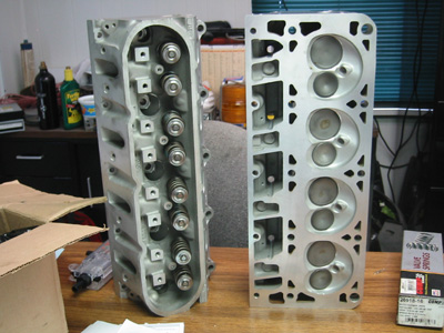
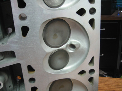
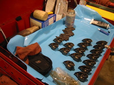
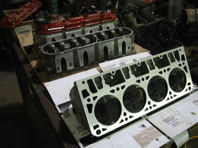
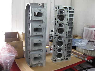
August 5th, 2006 - I decided to go with the GM "317" casting heads used on the 6.0L engines. These heads are aluminum with 74cc combustion chambers and valves a little larger than stock 5.7L LS1 engines. The larger combustion chambers will keep the compression ratio low to avoid detonation with a forced induction setup, and the larger valves will allow the engine to breathe more fuel and air. Brougher's Machine Shop in Clairton, PA just finished reworking the heads. They cleaned the heads, installed new valve seals and polished the combustion chambers to prevent carbon buildup inside of the chambers. They also installed stiffer springs and light-weight titanium retainers from Comp Cams. The stiffer springs and lighter retainers will guarantee accurate valve control at high RPMs.
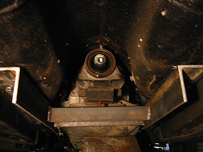
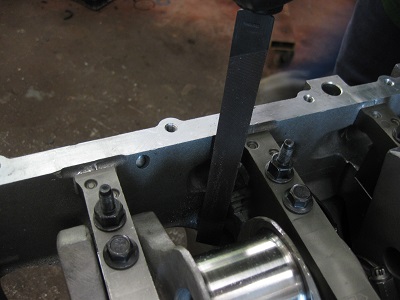
September 3rd, 2006 - Today we tried to finalize the location of the engine and transmission in the chasis. The wider 4L80E transmission (as opposed to the usual 4L60E) was keeping me from moving the engine deeper into the firewall while contact between the steering rack and oil pan sump was stopping me from moving the engine farther forward. Something had to give - either the oil pan or the transmission tunnel. I removed the oil pan from a junk engine and my brother and I mounted the engine and trans onto the engine motor mounts. We jacked up the tail housing of the trans until the output shaft was within about two degrees of the rear end input shaft. Making sure these angles are close is critical to preventing vibrations and extra wear on U-joints. The 4L80E was a tight fit, so we marked the areas that contacted the transmission tunnel with a marker and will use a hammer to make some extra room.
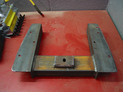
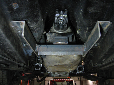
September 16th, 2006 - In order to get better access to the transmission tunnel, we removed the engine and trans and put the car up on the rack. We then pounded in the tight spots of the transmission tunnel with a hammer and reinstalled the engine and trans. With adequate clearance, we were able to bring the transmission output shaft within 1.5 degrees of the rear end input shaft. My fiance's father Dave quickly measured and drew plans for a crossmember to support the transmission. Download PDF drawings of the 4L80E transmission crossmember used in this swap. (Left click the link to view, right click the link to download.)
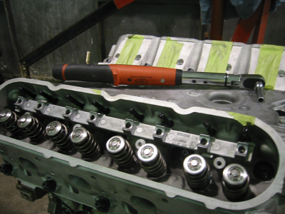
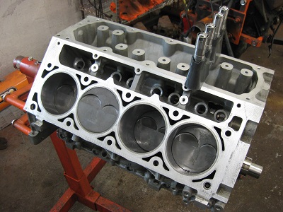
November 25th, 2006 - Today we started turning the shortblock into a longblock. Drew and I groud down a piece of the block and installed an LS6-style valley cover which has as a built in oil separator and breather tube. This setup is found on the later LS1 and LS6 engines and will help control engine vacuum and crank case pressure. We also installed a set of new GM roller lifters and modified lifter guides. The roller lifters roll along the camshaft as opposed to the sliding flat tappet style found on the original small block Chevy. We drilled holes in the bottoms of the lifter guides to prevent oil from collecting. Next we installed a set of ARP head studs. These studs are recommended for extreme use and will keep the head from lifting off the block under boost. Finally, we installed a set of standard GM steel head gaskets, installed the heads and torqued down the head bolts in the OEM sequence.
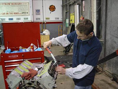
December 23rd, 2006 - Installing the valve train turned out to be pretty easy. Drew and I installed a set of Comp Cams Magnum 7.40" hardened pushrods. Stronger pushrods are required to compress the stiff aftermarket springs installed on the heads, especially at high engine speeds. The pushrods are hollow to let pressurized engine oil travel from the hydraulic roller lifters up to the rocker arms. Next, we installed the rocker guide plates and the rocker arms. The LS1 rocker arms are self locating, so no valve adjustment was required. Drew and I also removed the engine and beat in the transmission tunnel with a hammer, to give the transmission a little more room.
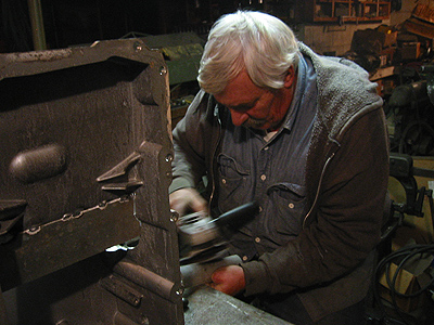
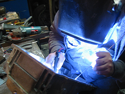
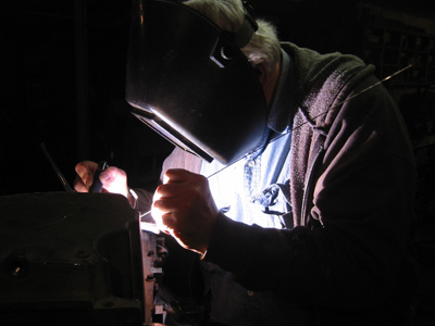
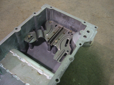
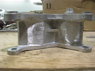
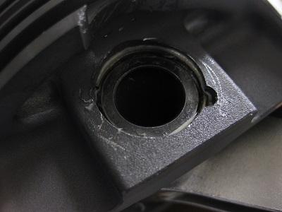
December 26th, 2006 - Modifying a cast aluminum oil pan to clear the Jag steering rack was beyond my ability, but not my Uncle Buck's. I started with a Cadillac CTS-V oil pan because it was closest to the shape I needed. My brother and I used engine degreaser, a scrub brush and a steam cleaner to get the pan as clean as possible. Next, we ran it through the dishwasher (with regular dish detergent) to get out all of the solvents and residues that will cause problems when welding. The next day, Buck cut the pan using a cardboard template and tacked in two pieces of aluminum plate and a piece of aluminum pipe with his TIG welder. A quick test fit shows that it is a perfect fit!
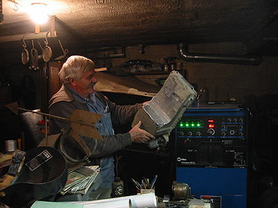
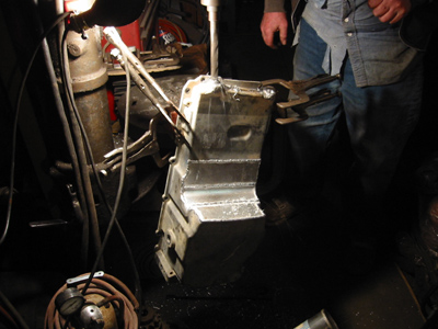
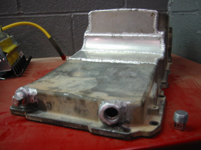
March 10th, 2007 - Now that a proper fit has been confirmed, it's time to weld the rest of the pan. We tightened the pan down to a junk LS1 block to keep it from warping. The pan will get very hot while welding, and as the pan cools it will try to warp. Hopefully keeping it tightened to the block during heat up and cool down will keep the pan from warping. We then attached, drilled and tapped two 3/4" NPT bungs onto the front of the oil pan for the turbo oil returns. Buck also fit a piece of square pipe into the trans cross-member, letting us adjust the mounting height of the transmission mount.
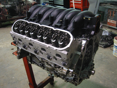
April 7th, 2007 - Today we started to finish up the rest of the engine. On the top of the engine we installed the steam vent tubes and a Z06 Corvette intake manifold. This intake flows better over the entire RPM range than the original LS1 intake and even the LS2 intake. It was used on the 5.7L Z06 Corvettes and the late LS1s. On the bottom of the engine, we installed a new oil pump, a windage tray and the oil pump pickup tube. The windage tray scoops air off of the rotating crankshaft, reducing drag and cutting down turbulence inside the engine. It required minor modification to fit the pickup tube. The oil pickup is from a Cadillac CTS-V and mounts directly to the oil pump.
April 28th, 2007 - Mounting the engine covers and oil pan was a little tricky. First I installed new seals in the front and rear engine covers. The rear engine cover went on the easiest and lined up flush with the oil pan mounting surface. The front timing cover slid over the crankshaft snout, and required us to install a crank pulley to properly locate the cover. Finally, we carefully installed the oil pan, making sure to keep the rear mounting surface flush with the back of the engine, as the LS1 pan also mounts to the transmission bell housing. The baffle shown in the picture was originally from a Corvette oil pan, and was hacked down to clear the CTS-V pickup. Hopefully it helps to keep the oil in the bottom of the pan!
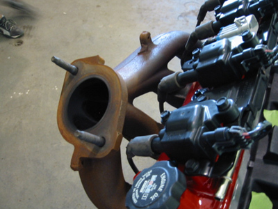
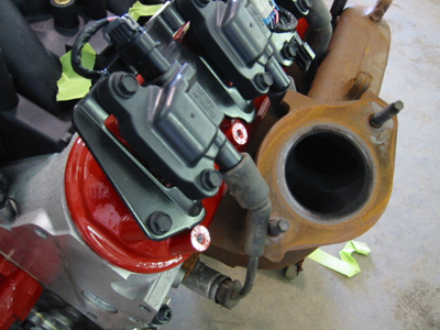
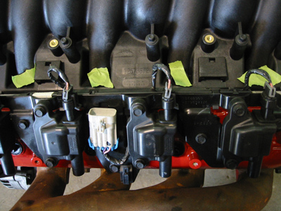
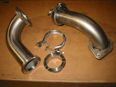
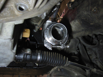
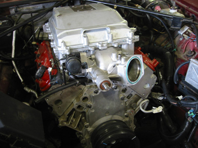
May 26th, 2007 - It's finally starting to look finished! The valve covers, coil packs, water pump and A/C compressor are now installed. The valve covers and water pump got a coat of hi-temp brake caliper epoxy paint from G2 USA. I also went through the engine and installed the drain plugs and the remaining sensors. However, today was a day of "three steps forward and two steps backward." It turns out I need a longer water pump pulley, an alternator bracket, and different exhaust manifolds. As shown in the pictures, I plan on dumping the exhaust forward and up. The idea is to use this setup to feed a set of turbochargers located in front of the accessories. It turns out that the flipped Cadillac CTS-V exhaust manifolds interfere with the coil packs on the driver's side. I will now have to experiment with different exhaust manifolds and try to find one that will give my coil packs some breathing room and allow me to run spark plug wires.
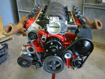
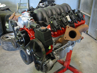
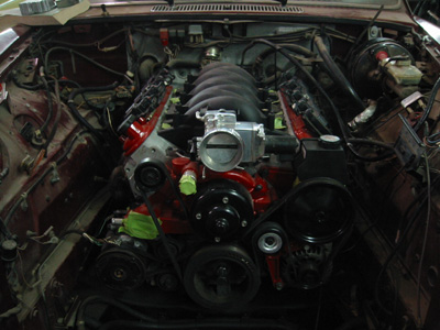
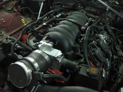
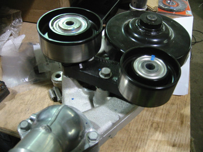
June 30th, 2007 - I think I can finally say that all of the mechanical parts of the engine are done. I still need a nice ruler to make sure the crank pulley is located within factory spec before I tighten it down. These pictures show some new additions, such as the polished drive-by-wire throttle body. The throttle body blade is controlled by an electric motor rather than a throttle cable, allowing the computer to control all possible variables of the fuel/air mixture. I also installed the water pump, power steering pump, alternator, idler pulley and tensioner pulley. The accessories that sit on the top of the motor were painted, while the unsung heros (alternator and A/C compressor) will be working out of sight in the depths of the engine bay. Attached to the engine is a set of LS-style cast iron truck manifolds. I think I am going to stick with the Cadillac CTS-V manifold on the passenger side (pictured in the previous post) and go with the above pictured truck manifold on the driver's side. Although not completely ideal, it leaves enough room to squeeze a set of plug wires in without touching the exhaust manifold. I also steam cleaned and painted the transmission bellhousing with high-temp grey primer.
September 27, 2008 - After over a year of no progress on the Jag, I will finally be working on the project again. Between getting married and starting a new career, I had to put my time and money to use where it was needed the most. The Jag has been busy holding parts for other projects that come and go in our shop. I am now putting together a list of bare essentials I will need to start and run the car, including a fuel system, drive shaft, air filter, gas pedal mount, wiring harness, computer, exhaust, transmission linkage, transmission cooler, power steering lines and cooling system. Yep, that's all. Check back over the next few months for updates!
February 2, 2009 - This weekend we put in the engine and trans for what we hope to be the last time. I hope it runs as good as it looks! Clearance between the 4L80E transmission and the trans tunnel looked very good, with at least 1/2 an inch in the tightest spot and room for the wiring harness plugs. In this position, the transmission output shaft seems to be within the required 2-3 degrees of the rear end's input shaft. Now that we have the right angle, we can weld the sliding pedestal on the trans crossmember to fix the angle and make any minor adjustments by shimming with plates and washers. It looks like custom headers will be required. ***Want to help me eliminate some of the excess Jag wiring!? Click here: Do I need these wires or can they go? ***
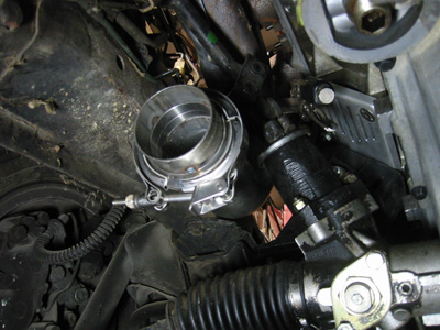
February 27, 2009 - We kicked things off by making a set of stainless steel flanges to bolt to the exhaust manifolds. We used 3/8" stainless 304 grade bar, and cut out a pattern to match the exhaust manifolds. Then we finalzed the transmission height and tacked the rest of the trans crossmember together. The final position found a sweet spot between exhaust manifold clearance, driveshaft yoke clearance, transmission tunnel clearance, and driveline angle. The transmission yoke fit great, and the driveline angle had an acceptable tolerance with a variance of around 2.5 degrees. Finally, we cut 2.5" 304 grade stainless steel mandrel-bent tubing to snake the exhaust out of the engine compartment. It was tight, and may require some minor adgjustments when fitting the catalytic converters. We also installed a set of stainless steel V-band clamps. These clamps press together two flanges using a V-shaped wedge built into the clamp. V-band clamps are often used on turbocharger exhaust housings and make a durable gasket-free seal that is easy to disassemble and reassemble. The clamps will make it much easier to drop the length of the exhaust system, allowing easy access to the transmission and driveshaft.
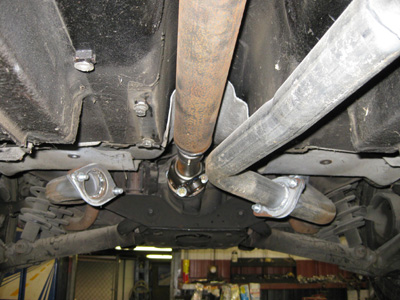
April 11, 2009 - I bought and installed a custom one-piece driveshaft (which replaced the Jaguar two-piece driveshaft) from Mark at Greensburg Machine & Driveline. The unit is made of 2.75" steel tubing with a slip joint in the rear portion of the shaft. Usually, this type of driveshaft has a slip yoke at the front of the driveshaft, which travels on the transmission output shaft. However, my 4L80E has a short output shaft, and we decided to bolt the yoke to the transmission and install a separate slip joint to accomodate any movement between the transmission and rear end. Even with the slip joint, the shaft is much lighter than the original Jaguar unit. It's also a pretty close fit - I don't think anything larger than 2.75" would work!
UPDATE: The 4L80E transmission that I have uses a slip yoke as opposed to a fixed yoke. Just because there is threaded hole in the trans output shaft does NOT mean it requires a fixed yoke! Unless you're 100% sure you need a fixed yoke, use a slip yoke on the trans output shaft!
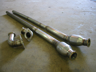
May 8, 2009 - This weekend, Buck and I measured, cut, and tacked together some exhaust. A set of Magnaflow metal subtstrate high-flow catalytic converters will keep things smog legal and quiet down the car while creating minimal backpressure. These 409 stainless steel gems are Magnaflow's top of the line converters, and ditch the traditional ceramic honeycomb in favor of a stronger, more performance freindly metal design. The rest of the exhaust is pieced together from 304 stainless tubing and mandrel bends. The diameter starts at 2.5" and necks down to 2.25" to keep cooling exhaust gasses flowing through the pipes at the desired rate. The smaller tube will also offer a slightly quieter exhaust note. Everything was TIG welded and ground smooth by Buck. We also examined the shifter linkage and thought through a couple of potential solutions.
June 6, 2009 - This week's focus was on the fuel system. I drained each tank and purged the fuel lines. To my surprise, the gas that came out of the drain plugs on the tanks (about 12 gallons) did not look too bad. However, the stuff that the fuel pump pushed out of the fuel lines was pretty dark. Having the car stored indoors for the last 5 years proably kept the fuel system from getting worse than it did. I poured a few gallons of good gas in each tank and ran the pump until the gas came out a pale yellow. I then changed the fuel filter and replaced all of the pressure hoses in the trunk with SAE 30R9 fuel hose, and replaced the worm gear clamps with sold nut-bolt clamps. The SAE 30R9 fuel hose is rated at around 100psi, and will accomodate the 58psi that the pressure side of my fuel system will run. Traditional worm gear clamps can tear the outer lining of the hose, so I bought nut-bolt clamps specific to my hose size. These provide the ideal clamping pressure when fully tightened, and their smooth clamp faces will not tear into the hose. I then ran some new fuel through the lines and everything seemed to work without leaking. The real test will come when we hook up the fuel pressure regulator, which will load up the fuel lines to 58psi!
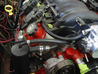
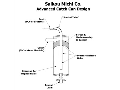
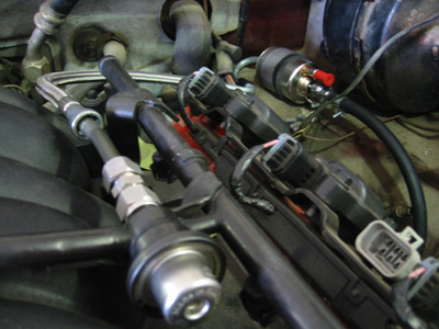
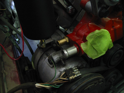
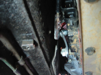
August 15, 2009 - Today I installed the PCV system and part of the fuel system. The PCV system (Positive Crankcase Ventilation) maintains a vacuum in the crank case to reduce piston pumping loss, promote ring seal, etc. The natural intake vacuum is used to create the vacuum in the crankcase. In addition to the Corvette PCV valve, I used a catch can made by Saikou Michi to separate the oil from the vacuum air before it is pulled into the intake. This will prevent oil mist from running through the intake and fouling the plugs, especially at high engine speeds. For the fuel system, I mounted the Corvette fuel pressure regulator/filter unit by the brake booster and bent a piece of steel tubing to reposition the outlet. The fuel rail inlet needed to be cut because it interfered with the newer LS2 coil packs. I used a stainless Swagelok fitting from Washington Valve & Fitting Co to join what was left of the fuel rail inlet to another piece of slightly bent tubing. The result kept the Corvette braided steel fuel line from contacting the engine. All of the fittings on the fuel pressure regulator/filter and braided steel line were GM quick-connect fittings. Male ends require a special flaring tool, and female ends a special adapter. Uncle Buck tapped the water pump and we installed a threaded hose end. This replaces the pressed hose end that I managed to pull out when taking the water pump out of the Corvette.
October 17, 2009 - Buck and I put the car up on the rack and put several hours into ironing out the transmission shifter linkage. We had to use trial and error to get the proper "throw" on the gear selector, so that the positions on the shifter in the car matched the gear selector positions on the transmission. The end result was a new arm on the trans gear selector and an adapter that interfaced the shifter cable with the new arm. The adapter is a piece of tube with a threaded stud and two set screws. This design gave us room for adequate adjustment and clearance against the trans tunnel and the transmission. A nylon lock-nut and some nylon washers will keep the shifter in place while letting it rotate smoothly as the shifter is shifted. We secured the shifter cable directly onto the transmission using a threaded hole that was originally intended for a heat shield. The shifter positions in the car line up with the R, N, D, 2, 1 on the center console, while the park position is slightly past the P.
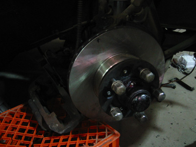
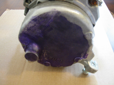
November 11, 2009 - The front brakes were completely gone. This is no surprise: the XJ6 uses a vented brake system, which allows oxygen from the atmosphere to come in contact with the brake fluid. Over the 7 or so years that the car has been sitting, the brake fluid successfully absorbed enough oxygen from the atmosphere to do some damage. Removal of the dust boots revealed pistons completely seized with rust. The seized calipers, coupled with rotors worn down so far that a large ridge was created around the perimeter of the disc, made it difficult to pull out the pads and remove the calipers. Rather than try to service these parts, I installed a set of Brembo OE replacement rotors and ordered a set of hoses, pads and reman'd calipers. Before installing them, I will bleed the entire brake system to prevent my new parts from seizing.
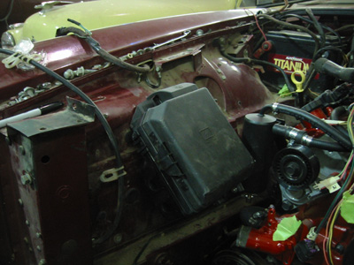
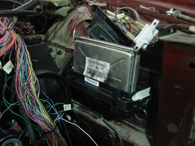
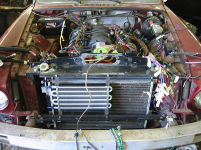
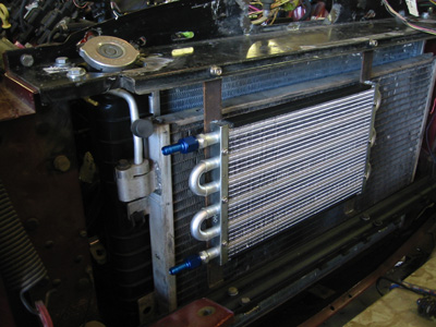
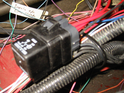
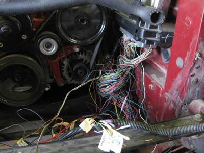
December 5, 2009 - The electrical system and the cooling system both compete for space in the engine compartment, so I worked on them at the same time. The radiator, condenser and fan setup is from a 1999 Camaro Z28. Once you mount the radiator, the condenser slides on the front and the fans slide on the back - it's really pretty easy! The whole assembly fits great where the original Jaguar equipment was located. The rubber mounts on the top and bottom of the radiator make the unit about 1/4" too tall, which will probably require me to shave some material off the mounts. I used a C5 Corvette PCM mount to fasten the PCM to the driver's inner fender, immediately behind the fan. A 2008 Impala fuse box, which has all of the circuits I will need to operate the PCM, transmission, fans, and even some other items (headlights, etc) was mounted opposite of the PCM with a homemade bracket. The wiring harness, from a 2006 Sierra 2500HD/4L80E, is still a work in progress, as I need to lengthen the wires running to the fuse box and shorten some that cover too much ground. To make the job manageable, I downloaded all of the schematics for the different cars I am using (2006 Sierra, 1999 Camaro Z28, 1998 Corvette, 2008 Impala) from the local library!
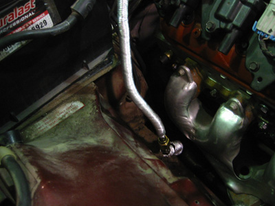
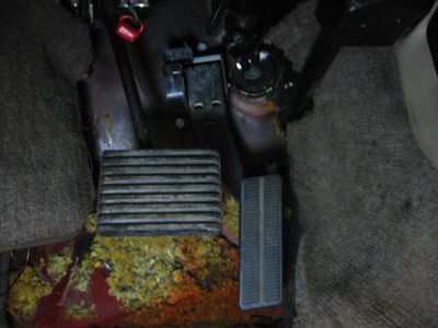
March 10-12, 2010 - The focus this week was on the fuel and electrical system. After removing the old Jaguar computer control wiring from the passenger side of the engine compartment, I began plumbing the remaining fuel lines. I attached the Jaguar chassis fuel line on the passenger side of the engine compartment to the regulator on the driver's side using a hard steel brake line, a few brass 45-degree SAE tube fittings, and a 45-degree flaring tool. I tested the system and there were no leaks! I then installed some heat-reflective shielding around the fuel lines and the brake lines to protect them from heat coming off the exhaust manifolds. Next, I identified and hooked up the Jaguar headlight wiring and installed the new 7" headlight assembly from Andrew at Jaguar Specialties. The larger 7" headlights replace the old 5.75" headlights giving the car a better look and the driver better night-time visibility. I had my first Jaguar electrical system "moment" after I hooked up the headlights: As I pushed the headlight relay and the fuse panel back on to the fender to mount it, the headlights began intermittently going out. After checking all the connections, it turned out to be a corroded fuse contact. I sanded the contacts and the connection was restored. For this reason, my ultimate goal is to bring the headlight system over to the GM fuse box, but I will focus on that later after the car is on the road. I also installed the Corvette drive-by-wire gas pedal, which turned out to be as easy as drilling two mounting holes. The hardest part was getting the insulation off of the floor pan and removing the existing gas pedal. With the pedal in place, it's starting to feel like a car again!
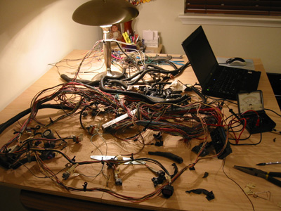
May 22-24, 2010 - After I hacked up the upper radiator support in an effort to clear the radiator cap, Uncle Buck took it off my hands and put in a smooth egg-shaped hole that not only allows the radiator cap to poke through the support, but also makes it easy to install and remove. He also took a piece of sheet steel off the center of the support and opened up an oval hole, which will allow us to feed the engine cold air from the front of the car rather than hot air from the engine compartment. After the radiator support, radiator, condenser, trans cooler brackets (thanks again Buck!), trans cooler, and electric fans were installed, I started on the wiring. The nicknamed "Franken-Car" wiring harness required me to lengthen and shorten wires from the truck harness to fit the Corvette layout. The truck harness sits higher than the Corvette and covers a geographically larger area, where the Corvette is more compact. As a result, most of my efforts have been spent shortening rather than lengthening. I also had to change over several connectors that different between the two cars, including those on the fuel injectors (yes, all 8) and the throttle position sensor. All splices are soldered and then sealed with adhesive-lined heat shrink tubing and a heat gun.
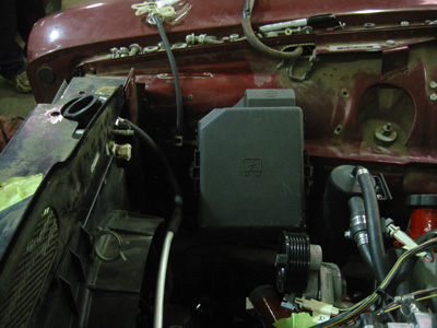
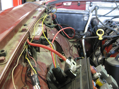
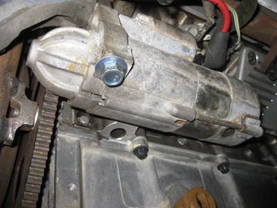
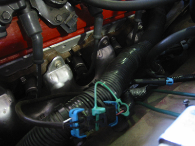
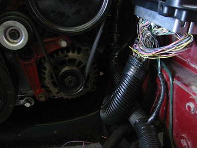
August 20-23, 2010 - At first glance, things don't look all that different - but a lot has changed! The relays and wires that ran above the battery and down the firewall are gone. These parts controlled the Jag fuel injection, fuel pump, engine controls, sensors, and starter. Now all of those functions are handled by the much more reliable Impala fuse box. I pulled the wires running from that corner through the fender, following the path of some still useful Jaguar wiring. Most of the wires that interface the powertrain with the Jaguar chassis travel through the fender, including all of the gauge sensors, fuel pump wire, and the ignition switch wires. Soon they will all be covered with black corrugated tubing. Staying with the GM theme, I bought and installed metri-pack 150 connectors, terminals and seals. These wiring assemblies are weatherproof, easy to reconfigure, and are used by GM on all of their current vehicles. By disconnecting the plugs, I will be able to pull the engine and harness out in one piece without cutting any wires. The connector assemblies require a special terminal tool and crimper to install. I also installed and wired in the engine side of the air intake assembly. I used a truck-style MAF/IAT sensor, and a 22-degree 4" rubber intake hose with a reducer on the throttle body side. This sweeps up just enough to reach my air filter assembly. I installed the starter, wired up a 6-gauge starter wire (only 20 inches long) and crimped on a new end. I also included a picture of the finished exhaust. I shortened the transmission dipstick tube and the dipstick so they would be well out of the way. The last picture shows the trans cooler quick-disconnect fittings on the side of the transmission. The clearance is too tight for the fittings I have, so I'll have to think of something else!
August 23, 2010 - Check out the video! (Press Play Button) The engine started right up after I connected a loose ground wire to the back of the engine block. The oil pressure came up after about 2 seconds. The car sounds pretty loud because the exhaust was pulled off one side to put the starter on. Apparently the wiring works, too. This is a great milestone!
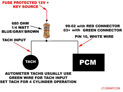
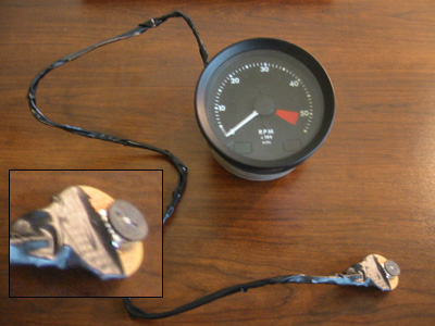
September 12, 2010 - Starting the car revealed a host of small issues that needed to be addressed. Among these was a dead tachometer. After doing some research, I found that some tachometers (especially aftermarket ones) require a stronger signal than their OEM counterparts. GM PCMs in 2003 and newer vehicles have a weaker tach signal than their earlier predecessors. To strengthen the tach signal, I will need to install a "pull-up circuit" also known as a "booster circuit." This will jump the 5v tach signal provided by the PCM to a 12v signal my Jag tachometer is used to seeing. To do this, a resistor is installed between a positive 12 volt source and the tachometer signal, as shown in the diagram provided by LT1swap.com. However, there has been some debate as to how strong of a resistor to use. I have seen suggestions ranging between 470 ohms and 4.7k ohms. It seems like they will all make the tach work, but a resistor that is too weak will cause the needle to flutter at low engine speeds on some tachometers. To address this problem, I installed a 10k ohm potentiometer (which is a "variable/adjustable resistor") in a spare Jaguar tachometer. Using this test tach, I will be able to experiment with different resistance settings by rolling the knob on the potentiometer, just like you would adjust the volume knob on your car radio. The potentiometer will allow me to vary the resistance between 0 and 10k ohms. Once I find a setting that makes the tach work smoothly, I will disconnect the tach, measure the resistance across the potentiometer, buy the closest carbon resistor to that resistance, and permanently solder it into the inside of my original tachometer.
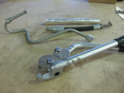
September 25, 2010 - Although most of the LS1 parts are generally compatible, mixing and matching engine parts from different cars can create some fitment issues. For instance, the Camaro power steering pump fit nicely to the right of the Corvette throttle body. Howevever, the high-pressure power steering line interfered with the throttle body motor. To work around this, I had to make a custom power steering line. I made a model of the tube with a piece of coat hanger and later made the final part out of 3/8" steel tube with an o-ring flare for the power steering pump. I connected the steel tube to the power steering hose with 3/8" JIC male crimp-on fitting on the hose and a tube nut, tube sleeve, and JIC flare on the steel tube. JIC fittings are high-pressure hydraulic fittings that use a 37 degree seat. They are almost identical to the aluminum "AN" fittings often used on aftermarket fuel systems. The steel fittings are less expensive than the aluminum AN fittings, and are suitable for high-pressure applications. I also started wrapping the engine wiring harness in black corrugated tubing and electrical tape, similar to the procedure used by most manufacturers.
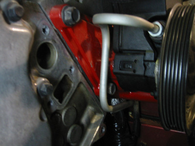
January 2, 2011 - This weekend I finished the power steering system, and it works great! You can see how the shape of the new tube compares to the shape of the original Camaro hose assembly. The routing of the pressure hose was pretty straightforward, but left very little room for the return line. I had to route the return from the steering rack towards the firewall, and then make a 180* bend and bring it back towards the power steering pump. There is about 3/8" of clearance between the lines and the engine pedestal, which I think should be enough. I also covered the hoses with reflective heat shielding. Even though the lines are somewhat close to the exhaust manifold, I expect most of the heat to rise off of the manifold (rather than fall onto the lines) and don't anticipate any heat-related problems. After getting the power steering hooked up, I torqued down the crank pulley, installed the accessory belt, and cycled a few quarts of power steering fluid through the system to purge out the old fluid sitting in the Jaguar rack. I also cleaned up some wiring under the hood and replaced one of the fuel level sending units so that the gauge will work in at least one tank.
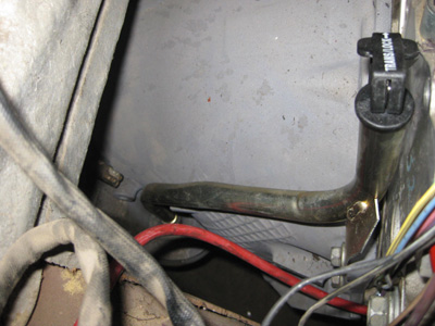
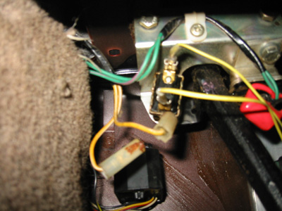
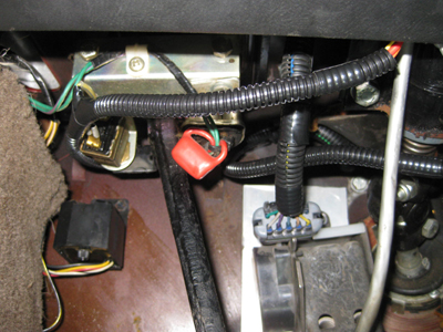
February 13, 2011 - This weekend was all about wiring. Aside from covering wires with black corrugated tubing and electrical tape, I pulled some important wires up to the firewall that eventually need to go into the cabin, including wires for the cruise control, speedometer, diagnostic port, check-engine light, and low brake fluid light. More importantly, I sorted out the "brake pedal status" wiring. In most GM vehicles, when the brake pedal is pressed, a 12 volt signal is sent to the criuse control module which disengages cruise. Likewise, when the brake pedal is not being pressed, a 12 volt signal is sent to the PCM, indicating that it is safe to lockup the torque converter, which improves fuel economy. I achieved both of these objectives using a single switch located on the brake pedal mounting bracket (pictured above connected to two yellow wires) known as the "brake operated switch." This is the switch the Jaguar cruise control uses to disengage cruise. Using a waterproof resistor relay, I can switch the 12 volt circuit from the PCM torque converter lockup wire (when the pedal is at rest) to the cruise control disengage wire (when the pedal is pressed.) I mounted the relay in the engine compartment so I would not hear a "click" every time I pressed the brake pedal!
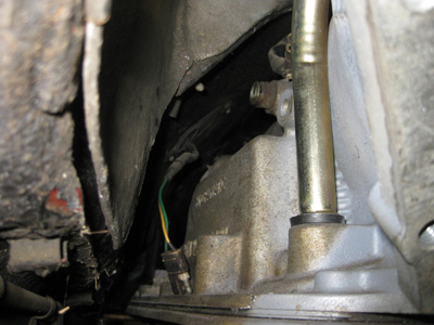
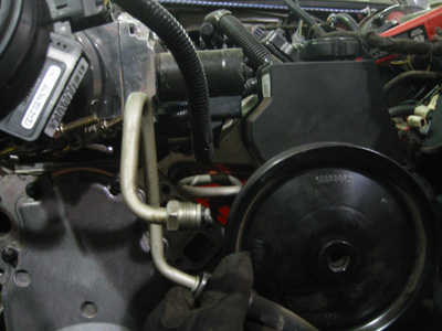
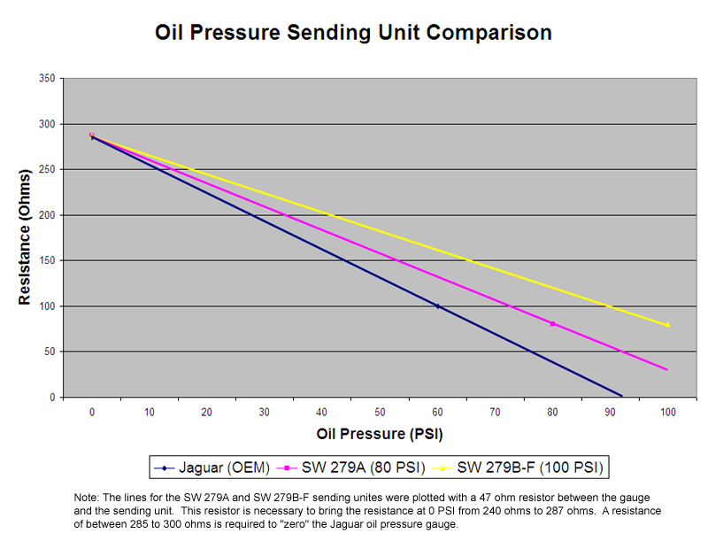
February 16, 2011 - When I last worked on the car, I was unable to fit the Jaguar oil pressure sender onto the engine. The OEM Jaguar sender uses Parallel British Pipe Thread (BSPP) and the hole I am using on the engine is metric. Unfortunately, I was unable to find a 12x1.5mm male to 1/8" BSPP female adapter that worked. Rather than making my own adapter, I decided to find an aftermarket sender. I stumbled across the Stewart Warner line of senders, which have a great reputation for reliability. They also have a high working operating temperature (300*F) which is important because I am mounting the oil pressure sender under the exhaust manifold by the oil pan. The Jaguar sender was prone to failure, and holding both in my hand at the same time, the Stewart Warner unit looked like the more robust design. Next, I made a chart that compared data points from the Jaguar sender to two Stewart Warner senders. The goal was to pick the sending unit with an output closest to the OEM Jaguar sender. After plotting out the data points, the SW 279A was the clear choice, and should make the oil pressure gauge read close to that of the OEM Jaguar sender, erring on the low side. While my chart has several shortcomings, the most notable is the shape of the lines. I was only able to find two published data points for each sending unit, which only allowed me to draw a straight line. The sender is a variable resistor (potentiometer) which would typically make a curved line on the chart as it goes through its operating range. If I had more data points, the line would probably look a little different.
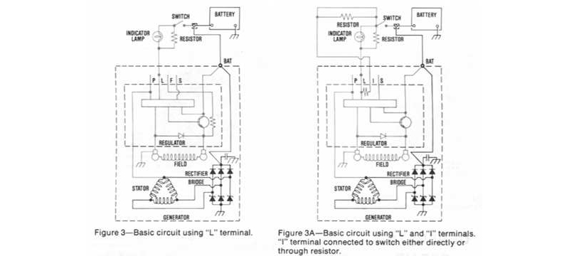
February 18, 2011 - Another headache I sorted out was the proper wiring of the 1999 Camaro alternator. The Camaro alternator is a 102 Amp Delco-Remy CS130D. The alternator is "internally regulated" and a field wire is not required. The only required wires are 1) a heavy charge wire that goes to the battery post, and 2) a thin wire that is switched to +12V when the key is turned on. This thin wire can also be used to activate the charging system fault indicator when wired to the battery trouble light on the dash. When the key is on and the alternator is not charging properly, the alternator will ground the thin wire and illuminate the battery trouble light. There are a few important points to note if you are wiring this CS130D alternator: 1) The thin wire must go to +12V, or the alternator will not charge. 2) The thin wire must have some resistance in it, between 33 and 500 ohms, either in the form of a resistor, a light bulb (e.g. the dash light), or both. 3) The thin wire can be connected to two different terminals on the alternator - the "L" or "I" terminal. The "I" terminal is used if you do not have a battery trouble light, and the "L" terminal is used if you do have a battery trouble light. For more information, see the Delco-Remy service manual hosted by alternatorparts.com. I have seen the wiring of this alternator discussed on several chat forums, but none of the discussion is as detailed or complete as the service manual!
February 26-28, 2011 - This weekend, I worked on the wiring that interfaces the PCM with the chassis. I ran the wires for the cruise control, speedometer, diagnostic port, check-engine light, and other wires into the cabin through a hole on the top of the driver's footwell. The Jaguar cruise control buttons should be fully functional using the GM cruise control system and discarding the Jaguar system. I had to run "hot-in-run" wires to the brake pedal switch and the Jaguar cruise control switch located in the center console because the GM TAC module is activated by +12V cruise control signals, rather than the ground signals used by the Jaguar cruise system. I also installed a small relay in the dash to switch the polarity of the cruise set switch located in the turn signal stalk, for the same reason. I covered everything with corrugated loom and electrical tape, and packaged it using wire ties and Jaguar wiring tabs. I also finalized the length of the wires traveling down the driver's side of the engine and covered them with corrugated tubing. This really cleaned up the engine bay. I then made a small bracket out of sheet aluminum that mounts to the back side of the head. The bracket lifts the harness several inches off the back of the engine and the driver's exhaust manifold. My next task in the engine bay will be to cover the wires going into the PCM.
March 25, 2011 - Trudging along with the wiring, I covered the main harness line that runs along the driver's side to the PCM with black corrugated tubing. I also taped and covered branches of the harness that go to various components. Keeping the wires from touching critical parts such as the brake lines, spark plug wires, power steering hoses, and fuel hoses was a challenge. Any contact could eventually lead to one thing rubbing through another, causing a failure.
April 9, 2011 - This weekend I cut a rather large hole in the trans tunnel and finished the transmission shifter linkage. My goal when starting this project was not to cut the trans tunnel, but because of the large electrical connector on the side of the 4L80E, I had no choice. What started as a small hole turned into a large slot, about 12 inches long and 5 inches high. In the end, this hole also allowed me to install a newly designed shifter linkage assembly. I thought I had the transmission linkage finished, however the design did not squarely engage the gear selector on the transmission - its range of motion was skewed. As a result, the shifter cable failed, and I had to replace it. My theory is that the metal end on the gear selector was rubbing up against the transmission tunnel, which placed too much stress on the cable. The new design squarely engages the gear selector, and retains the Jaguar compression-style cable end. I mounted the cable on a piece of 1/8" steel bar that I heated and twisted to the correct shape. (I plan on welding on another piece of metal and securing it with transmission pan bolt to keep the mount from moving around.) The finished product works well, and the action on the shifter feels great. At some point, I will need to cover the hole with sheet metal, and provide a small access plate should the shifter cable ever need replaced.
May 22, 2011 - Today, I finished the bundle of wires that runs along the lower core support between the PCM and the fuse block. This bundle also carries a couple relays, A/C wiring, and sensor wires that interface with the chassis on the passenger side. It is connected to the chassis wiring with Metri-Pack connectors, so I can easily disconnect the engine harness from the chassis if I want to remove the engine. I then installed the radiator, condenser, fans, upper radiator support, and hood. The radiator is from a 1997-2004 Corvette. It is the same as the Camaro radiator, except that the inlet and outlet hoses are in different locations, which better suits my conversion. The Corvette radiator also lacks a radiator cap, which means I will need a pressurized coolant surge tank instead of an overflow bottle. The Camaro fans and condenser slide onto the Corvette radiator just as they did with the Camaro radiator. I also wired the fans and ran wires for the horns.
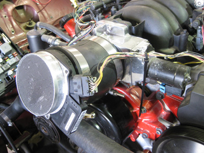
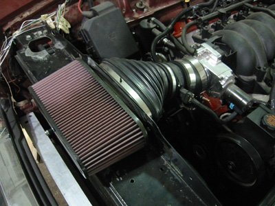
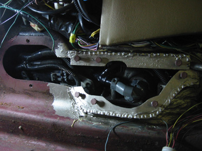
December 23, 2011 - This week, I addressed the hole in the transmission tunnel. I wanted a strong and permanent solution that would also give me access to the transmission wiring and shifter linkage. To accomplish this, I made a box out of 16 gauge steel and had it welded onto the trans tunnel in two parts. I also had nuts welded to the inside of the box so that I could bolt on the cover. I then primed, seam sealed, and painted the area with some leftover paint. Now, all I need to do is make a cover for the box. I also installed the air cleaner. This air cleaner started life as a K&N air filter kit for a Camaro. A shorter and wider base was cast out of carbon fiber to create a unit that will fit under the Jaguar hood. It is connected to the MAF with a snorkel tube from a Corvette. This setup will allow the car to draw cold air from the front of the car, rather than hot air from under the hood. The cold air is denser, and will allow the engine to create more power.
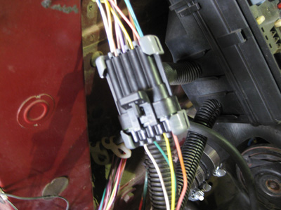
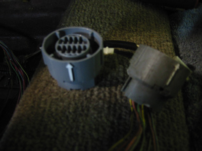
January 28, 2012 - Before making a cover for the trans tunnel box, I decided to finish the transmission wiring. I started with the bundle of wires connected to the round connector. This connector is the primary way that the PCM communicates with the transmission. Rather than cutting and splicing the wires, I shortened the wires by putting on an entirely new connector. This connector uses the 100W type terminals, as opposed to the metri-pack 150 commonly found on other GM vehicles. The 100W terminals are also found in the LS1 PCM connector. I bought all of the parts from mouser.com, cut the wires, crimped on the terminals, and assembled the connector. I also shortened the rear vehicle speed sensor (VSS) plug, which I believe uses weather-pack terminals. The finished product fits great.
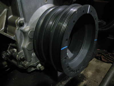
February 11, 2012 - I originally wanted to build the engine with turbochargers, but decided against it because of complexity, cost, and reliability issues. As an alternative, I started piecing together a supercharger system from a 2011 Cadillac CTS-V. More on that later. I started putting some of those parts on today. I took off the Camaro accessories and installed a CTS-V crank pulley. This pulley has the accessory and A/C belts closer to the engine, and has a third belt to run the supercharger. To help put the pulley on the crankshaft snout, I sat the pulley in front of a torpedo heater for about 5-10 minutes. The heat made the bearing surface expand, which helped the pulley slide onto the crankshaft snout much easier. After installing the pulley, I borrowed a Magnacharger crank pinning kit from my neighbor. (Small world!) This kit is essentially a jig that bolts onto the crank pulley and helps you drill a hole the splits the crank pulley and the crankshaft snout. After drilling and reaming the hole, I installed a 1/4" solid steel dowel pin. This pin keeps the crank pulley from spinning on the crankshaft snout, which is important on a supercharged setup. I also installed an LS3-style water pump. This pump holds a steel bracket with two idlers for the supercharger belt.
March 10, 2012 - When things are good enough, it seems like I just want to tear them apart and make them better. I bought a set of "799" core heads from a local salvage yard. These heads are generally the same as the heads I took off except that the combustion chambers are smaller. This should boost my compression ratio up to about 9.5:1, giving me a little more kick while still allowing a comfortable cushion for forced induction. Savani Auto Machine in McKeesport went over the heads, performinga a valve job and replacing a couple bent valves and damaged valve guides. I also installed a power steering pump from a 2004-2007 Cadillac CTS-V. Unlike the Camaro pump, this pump will line up with the new crank pulley. The flow is perfect at about 2.0 gpm, however, the pressure is a little higher than I would like, peaking at about 1,700 psi. To reduce the peak pressure, I changed out the pressure relief valve with a lower valve that I salvaged from a 2002 Camry pump. This should bring my maximum pressure down to about 1,250 psi, which is in line with the original Jaguar pump. I also used a Pontiac G8 alternator bracket to mount my Camaro alternator. The bracket required a little grinding but now fits fine and lines up the alternator with the new crank pulley. Finally, I wanted to test fit the CTS-V supercharger assembly on the engine. Think it will clear the hood?
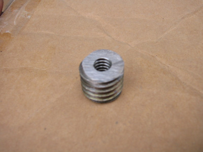
June 2, 2012 - Air conditioning is a priority for me. Come on - it's a luxury sedan! Of course, nothing off the shelf fit so I had to make something. I started with a Cadillac CTS-V A/C compressor bracket. It fit with some serious grinding, sanding, etc. This bracket lines up A/C compressor pulley with the A/C belt ribs on the crank pulley. The CTS-V compressor is too deep and interferes with the engine mounts, so I went with the LS-based truck compressor. The front of the compressor (where the pulley sits) is the same as the CTS-V compressor, but the back of the compressor is much shorter. The two front mounting points fit great, but the back two mounts did not line up. I had to cut off the rear upper mount because it interfered with the exhaust manifold, and drastically trim down the lower rear mount as well. I then made a threaded insert so I could put a bolt through the back of the bracket and tighten down the only remaining rear compressor mount. The threaded insert started as a 5/8" bolt, which I cut, drilled, and tapped with 1/4" threads. When I went to do my final install, I found out that the motor mount pedestal interferes with the back of the compressor, so I'll need to modify it when the engine comes out.
June 8, 2012 - After years of working on the car, I finally took it for a ride on the street! I finished the cooling system, wiring, and everything else required to run the car. The rebuilt CTS-V power steering pump wouldn't build any pressure - not sure why. I wound up putting the original pressure relief valve back in and it worked fine. The transmission was stuck in second gear, which is "limp mode" on the 4L80E. It turns out that at some point I bent in the transmission pan with a floor jack and broke the two shift solenoids behind the pan. I replaced the solenoids and the 4L80E internal wiring harness and the car shifted perfectly! The LS1 has a good power and torque, but I think performance suffers from 1) the slightly lower compression ratio, and 2) the shallow 2.88 rear end gears. The 4L80E first gear is 2.48, which isn't doing me any favors. On the plus side, it cruises under 2,000 RPMS at 65mph on the highway, which is really nice. The car sounds good too, even with half of the Jaguar exhaust still on the car!
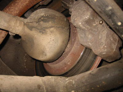
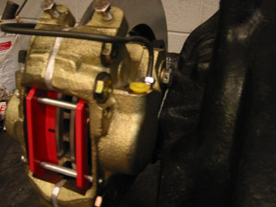
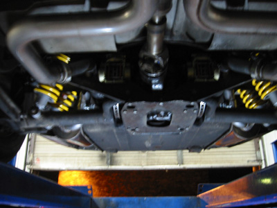
June 16, 2012 - Okay, the honeymoon's over - back to business! I am now starting to chase out the little bugs that plague the car. There are three big areas that need a little attention: brakes, suspension, and exhaust. I'm starting with the brakes because they're obviously important. The front brakes work great because I overhauled them a couple years ago. However, the rear right brake caliper is seized. That means that the caliper piston has probably rusted inside the caliper body and does not fully release (if at all) when you take your foot off the brake pedal. The result is that the rear right brake is always trying to stop the car. I tried several things, including greasing the pad pins, tapping the piston back into the caliper, changing the brake hose, and flushing the fluid, but nothing worked. I tried to remove the caliper with no luck. There's just no room under the car! Imagine trying to do the job through a paper-towel role - that is what it's like! Remember, the rear brakes on this car are mounted to the differential, as opposed to 99.9% of other car that have them out by the wheels. At this point, I think I have to drop the entire rear suspension assembly to get to the brakes.
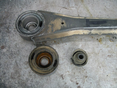
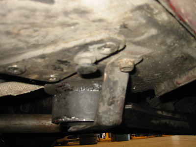
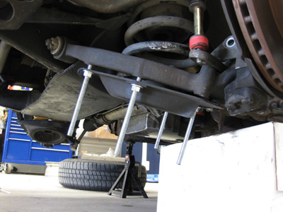
July 8, 2012 - I put the rear brakes on hold to collect parts, and started looking at the suspension. The car is over 25 years old, so most of the rubber bushings are badly deteriorating. As a result, the car is soft, and responds sluggishly to "spirited" driving. I replaced both steering rack tie-rod ends (not pictured) and that made a huge difference in steering response and cornering. I then turned my attention back to the rear suspension and replaced the rubber bushings in the radius arms. The radius arms connect the outer end of the lower control arms to the chassis under the rocker panels. They keep the wheels from lunging forwards under acceleration and backwards under braking. I pressed out the old bushings, which was a real pain, even with penetrating oil. I then pressed in the new bushings using some anti-seize compound so I can get them out again if necessary!
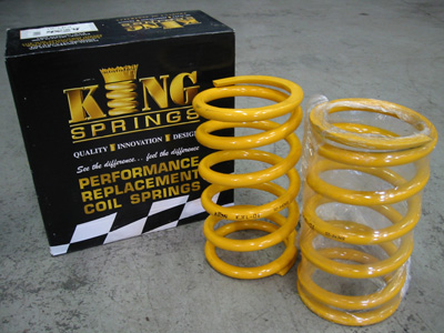
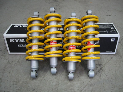
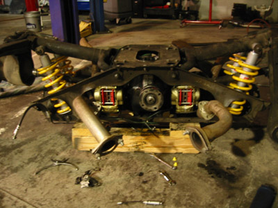
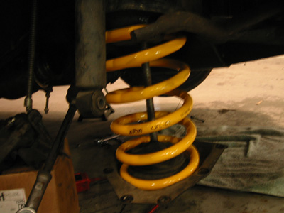
October 18, 2012 - In addition to the worn rubber bushings, the shocks and springs need some attention. The rear end is sagging, which means the rear springs are worn out. The car's ride is bouncy and soft, which means the shocks are tired. The front of the car has a shock and spring at each wheel, and the rear of the car has two strut assemblies on each side. To stiffen up the ride, I bought a set of King springs, which are about 20% stiffer than the original Jaguar springs. I also bought a set of KYB shocks which are slightly stiffer than the original shocks. I mounted the rear springs onto the struts, and will install them when I drop the rear suspension.
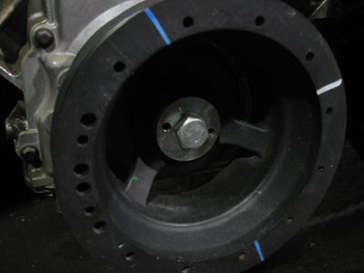
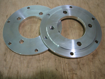
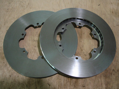
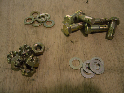
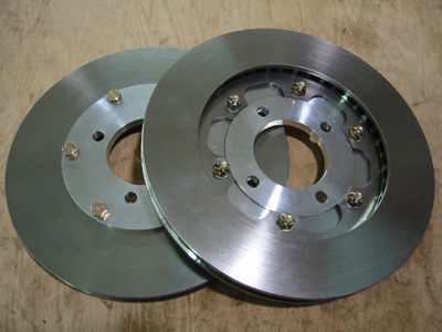
October 20, 2012 - Know what I like about the stock rear brake rotors? Nothing! That's why I decided to make a wider pair of rear rotors that will run cooler and as a result give me better braking performance. The new set of rotors are a two-piece design. This is frequently found on race cars. The two-piece design features and aluminum "hat" and a cast iron rotor. The hat's purpose is to support the rotor and dissipate heat created by brake use. The cast iron rotor is squeezed by the brake pads, which as a result of friction, generates heat and slows the car. I had the hats machined out of 7075 aluminum alloy, and had a set of custom cast iron rotors made by Hoerr Racing. I put the pieces together using 5/16-24 aircraft hardware known as "AN shear bolts" from B&B Aircraft Supplies. These are strong bolts that are available with a grip size (the smooth part of the bolt) in 1/8" increments and with shafts drilled for cotter pins. I also used washers and castellated nuts. The finished assemblies look great. Large parts of this design were borrowed from this article on the jag-lovers.org website.
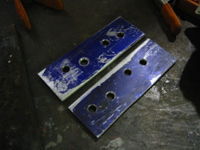
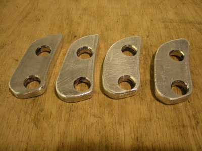
October 21, 2012 - To accommodate the wider rear rotors, I needed to widen the rear brake calipers. The stock Jaguar rotors were 1/2" wide and the new rotors are 3/4" wide. Therefore, I needed to widen the calipers by 1/4". I unbolted and split the calipers, and made 1/4" spacers to fit between the two pieces. The spacers started as a piece of scrap aluminum angle that I cut into 1/4" flat bar. I then drilled and countersunk the holes on a drill press. After that, I marked each piece, cut it out with an angle grinder, finished the shape with a table disc sander, and smoothed the corners with a carbide burr. I installed the spacers between the caliper halves with Grade 8 bolts that were 1/4" longer than the original bolts.
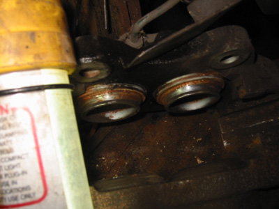
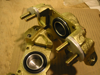
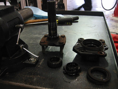
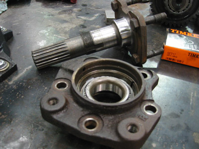
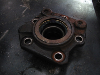
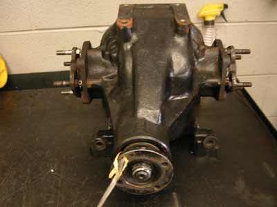
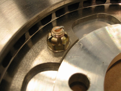
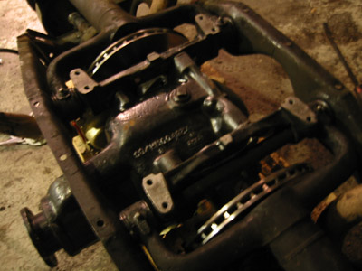
October 26, 2012 - While working on the rear suspension, I decided to swap out the existing open differential for a used limited slip differential. An open differential will allow one tire to slip under heavy throttle, resulting in poor overall traction and poor acceleration. A limited slip differential uses clutches to make sure that neither tire alone will slip under heavy throttle, resulting in far more traction and better acceleration. The gears themselves had no visible wear so I left them alone. I decided to change the rubber seals. I first pulled the pinion flange and changed the pinion shaft seal. I then pulled out the stub axle assemblies to inspect the bearings and change the stub axle seals. While changing the stub axle seals, I damaged and therefore replaced one bearing. The other bearings looked great. I also had to replace two studs on the stub axle flanges because of damage to the threads. After fully reassembling the differential, I used stainless steel .041" lockwire to secure the stub axle mount bolts and the lower control arm mount bolts. The safety wire is twisted from one bolt to the next so that no bolt is able to loosen on its own. I also secured the nuts on the brake rotors with cotter pins so they would not come loose.
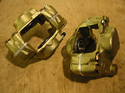
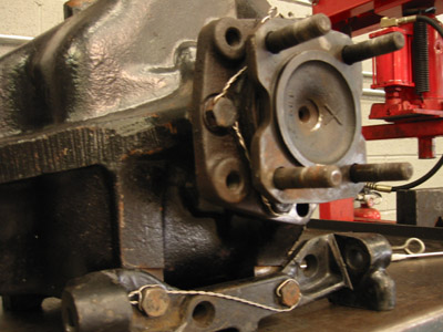
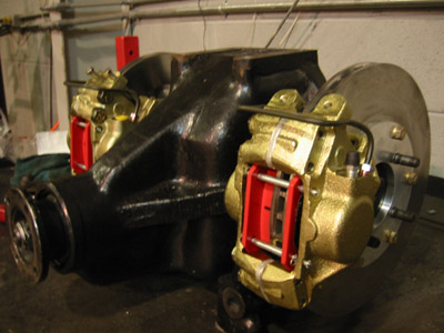
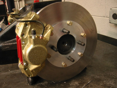
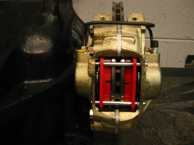
November 1, 2012 - Here are some pictures of the assembled differential unit. After a little bit of filing and sanding, the rotor assemblies fit nicely onto the Jaguar stub axle flanges. The modified calipers went on with very little room to spare. However, because the caliper halves are now 1/4" farther apart, some of the caliper hardware had to be changed. The pins that secure the brake pads in the caliper were now 1/4" too short, so I used a set of longer pins designed for my Jaguar's front brakes. I also made new crossover tubes, which carry the brake fluid from one side of the caliper to the other. I used a set of EBC RedStuff brake pads which are designed for heavy fast cars. Finally, I installed safety wire on the caliper bolts to keep them from backing out. If you're familiar with the Jaguar brakes, you probably noticed that the parking brake calipers are not pictured. I plan on refurbishing those at a later date and installing them when the differential is in the car.
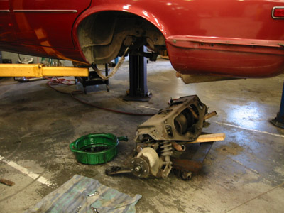
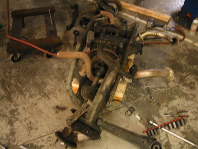
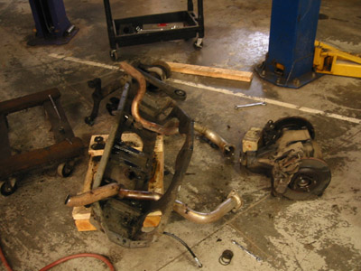
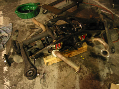
November 3, 2012 - The inevitable finally happened - the independent rear suspension assembly (IRS) was removed for service. It came out pretty easily - the radius arms, exhaust, driveshaft, brake line, and parking brake cable were all removed or disconnected. The car was lowered to the ground and the four rubber mounts that hold the cage to the chassis were unbolted. After that, the car was lifted up while the IRS remained on the ground. We took off the top bolts and rolled it over to finish stripping off the tie plate, lower control arms (LCAs) and axles. The old differential was then rolled out and new differential was rolled in. The new strut assemblies were also installed. I think the hardest part was removing and installing the steel inner bearing shafts that go through the cage, LCAs, and differential. These shafts needed beat in and out with a hammer. The grease seals for the needle bearings in the LCAs had about 4 parts for each seal, which kept on trying to fall apart as the shafts were reinstalled. Notice how the mess just grows and grows! Reinstalling the IRS cage was a little trickier but not too bad. I had to tighten a few leaky caliper fittings after the differential was installed, which took about an hour due to limited access to the fittings. The rear of the car is now noticeably more responsive, but I will not know just how good it is until I replace the front shocks, springs, and all four ball joints!
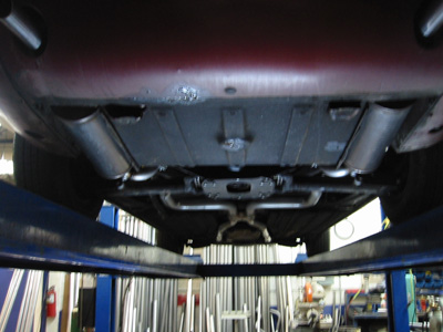
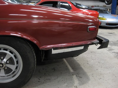
November 15, 2012 - I had a custom stainless steel exuast system made by Mandrel Bending Solutions (MBS) in Pasadena, Maryland. As you probably guessed, the system features all mandrel bent bends instead of crush bends. Crush bends, which are used by most exhaust builders, partially collapse the tube when bending it, creating less flow area and thus restriction in the system. MBS has a mandrel bending machine on-site, producing smooth bends that keep the circumference of the tube constant. The new system picks up a few feet behind the catalytic converters, runs through a Magnaflow X-pipe, through the rear differential, and then through two Magnaflow straight-through mufflers. The car has a deep quiet idle, purrs at cruise, and makes some noise under heavy throttle. The new system is 2.25" with the exception of the pipes that go through the rear suspension, which neck down to 2". The somewhat small 2.25" pipes and the large straight-through mufflers keep the car as quiet as possible while still supporting up to 700hp. The 2" sections are after the X-pipe where the left and right exhaust banks mix, so the smaller diameter will not hurt performance.
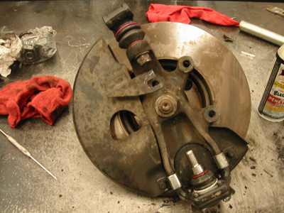
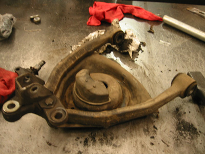
November 22, 2012 - The front suspension was in dire need of service. The ball joints were badly worn and needed replaced. Most of the rubber suspension parts were also shot, so I decided to replace the rubber control arm bushings with polyurethane replacements. The poly material is harder than rubber, and makes the car more precise on the road. The job was terrible! I had to remove the entire lower control arm assembly to change out lower control arm bushings. I also installed a King Springs spring, which is slightly stiffer and lower than the factory originals. The lower spring perch did not want to seat back into the control arm, so I had to use a strap and a ratchet to pull it over. For the next side, I will use some pilot studs to line up the spring perch with the control arm before I put tension on the spring. I've only done one side, and even without an alignment, the difference is enormous. The car is much more confident on the road and stable in the turns.
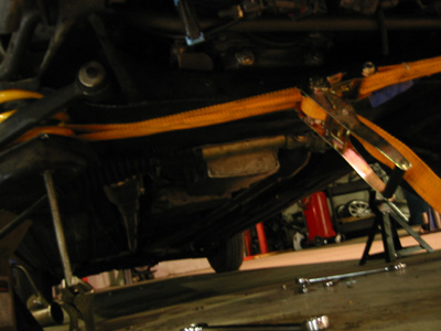
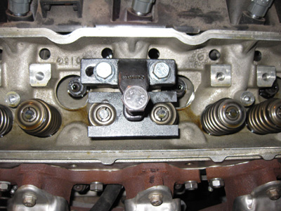
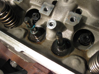
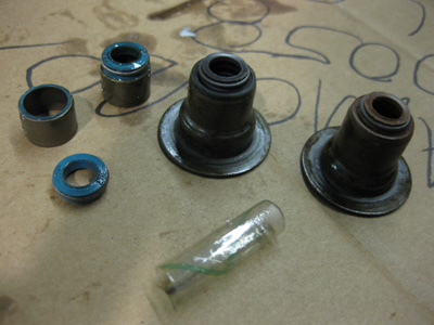
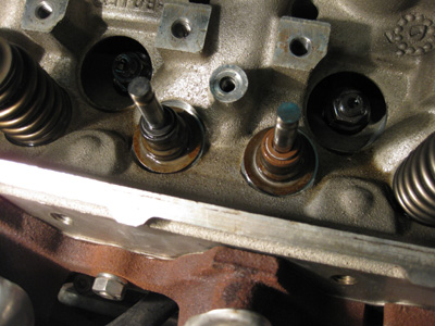
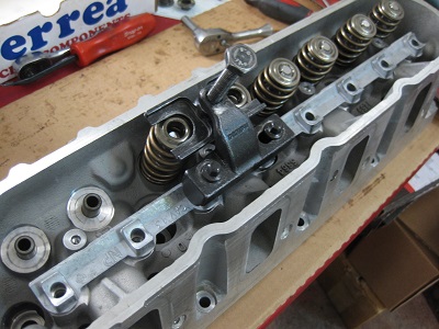
March 23, 2013 - I noticed that the car was using oil - a lot of oil - about 1.5 quarts every 100 miles. The problem got worse as I drove the car. The symptoms were consistent with bad valve stem seals - a puff of smoke on startup, and smoke under heavy throttle. This did not make sense because the heads were recently remanufactured. I took the driver's side valve cover off and discovered four seals which completely failed. The rubber (actually Viton) gasket material had separated from the base of the seal assembly. A few other seals were starting to rip but had not yet separated. The other bank also had a few failed seals. I compressed the springs, removed the locks and keepers, removed the springs, and replaced all of the seals with new ones of the current OEM design. The car no longer burns oil. I still do not know why the old seals failed. My only suspicion is that perhaps the ridges at the top of the valve stem were not covered when the seal was installed, creating small tears in the seals that eventually led to failure.
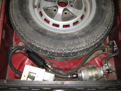
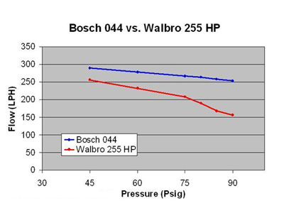
April 20, 2013 - Over the last 500 miles or so, my fuel pump began giving me trouble. It started with an intermittent "hoot" sound, like there was an owl was in the trunk, and eventually turned into a high pitched whine. I decided to replace it before it stranded me. My best choices were the Bosch "044" and the Walbro GSS342 255LPH. The Walbro is a good pump, but the Bosch 044 pump provides a slightly higher volume of fuel (enough to support 700 wheel HP) at a higher fuel pressure. The LS1 fuel system runs at about 58 PSI, which is on the high side. However, after my supercharger is installed, the fuel pressure will increase to counteract the boost pressure working against the injectors in the intake manifold. Simply put, if my supercharger peaks at 12 pounds of boost, my fuel pump will need to supply the same amount of fuel at about 70 PSI. For that reason, I went with the Bosch 044. The only real tradeoff is that the Bosch pump is noisier than the Walbro pump, so I wrapped the pump in closed cell foam and may add some acoustic material around the spare tire well in the future. I also installed some new fuel hoses with Fragola AN fittings and a Trick-Flow fuel filter on the inlet side of the pump to keep out debris. Unlike some filters, the element is a stainless steel cartridge and has plenty of flow area to minimize pressure loss.
UPDATE: It turns out that the Bosch fuel pump flows too much fuel for the Jaguar fuel system. The valves that direct unused fuel back to the fuel tanks are very restrictive. This restriction keeps the fuel pressure from coming down to the 58 PSI required by the LS1 engines. As a result, I wound up taking out the Bosch pump and installing the Walbro pump. It is very quiet - I hope it will supply enough fuel for the supercharger!
August 16, 2013 - I finally got around to rebuilding the front suspension on the other side. I used pilot studs to decompress the old springs and install the new King springs. This method was much better than using a single piece of threaded rod through the upper and lower spring perches. I also changed out all of the bushings and both ball joints. Again, the ride improved!
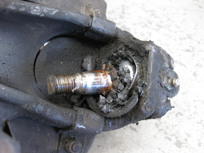
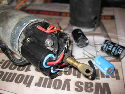
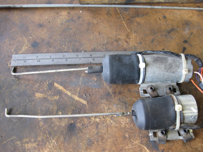
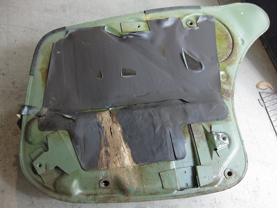
September 13, 2013 - I wanted remote power door locks so I had to install some additional hardware. The later XJ6 cars did not come with a solenoid unit to operate the lock in the driver's front door. Instead, they came with a smaller switch-only unit. To get power locks in that door, I had to install one of the earlier combination solenoid-switch units. The one I bought was used and did not work. After a little testing, I determined that the capacitors were bad. I installed new capacitors and the solenoid came back to life! Before installing it in the door, I had to shorten the bar that attaches to the lock, as the new solenoid-switch unit was longer than the original switch-only unit. I ran wires from the solenoid to a newly installed wireless entry controller and finally had remote power locks!
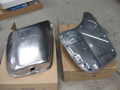
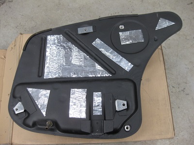
November 19, 2013 - Rust finally got the better of my fuel tanks. In addition to the leak on the driver's side tank, rust was also clogging the fuel filters. I bought two new steels tanks, coated them with rubberized undercoating, and applied a self adhesive vibration dampening material to both sides of the tank. This material changed the tone of the tank from a hollow "bong" to a tight thud. I then replaced all of the unseen hoses and carefully reinstalled the tanks. This is not a job I ever want to do again!
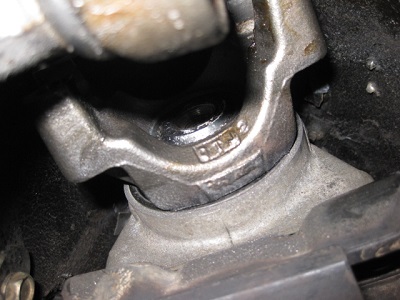
December 7, 2013 - Due to at least one of many potential causes, the rear case bushing in my transmission wore out. The output shaft wobbles badly. This could be due to a variety of reasons, including loose rear end input flange bolts, two slip yokes in the same driveshaft (oops!), and the rear suspension cage lurching forward under hard acceleration which pushes the driveshaft into the trans tunnel. I used a fixed yoke instead of a slip yoke on the trans, which caused the yoke to ride on the rear edge of the tailshaft. I pulled the transmission out. A friend of mine rebuilt the internal components and I installed a shift correction kit from Superior Shift. Because the transmission is computer controlled, the shift correction kit did not make the shifts harsh or rigid. Instead, the kit allows you to run higher line pressures so that the clutches will not slip under heavy load. I also had a new driveshaft made by the folks at Northern Virginia Supply in Newington, VA. This driveshaft incorporates a slip yoke on the transmission side instead of a slip joint in the shaft itself. The shaft turned out great and everything seems to be back to normal!
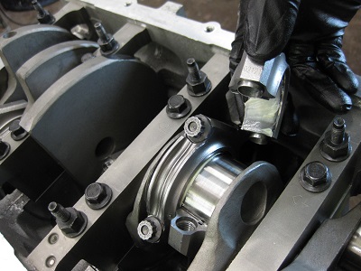
April 5, 2014 - Remember the CTS-V supercharger plan? That is not going to happen. I must have measured incorrectly because the supercharger did not clear the hood. I sold it and decided to build a naturally aspirated 408ci (6.7L) stroker motor. The extra stroke will generate much more low end torque to help my heavy shallow-geared car get off the line. The extra cubes will also help with top end. I started with a used aluminum LS2 block and had it bored & honed .030" over to 4.030. I purchased a 4.00" Eagle forged steel crank, Eagle forged steel rods with ARP rod bolts, and Mahle -4cc 4032 flat-top pistons and rings. The compression will be about 10.9:1 with LS3/L92 heads and a stock head gasket. We installed the crank with Clevite 77 bearings and checked the clearances with plasti-gauge. Everything was right within spec at .002".
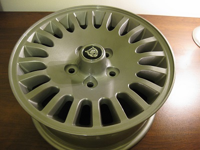
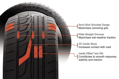
May 9, 2014 - The wheels were a little dated and the tall stock tire size was not the best choice for a performance car so I decided to get new wheels and tires. After looking through many OE and aftermarket options, I bought a set of used 16x7" wheels from a 1997 XJ6 and had them powder coated metallic silver by Justin at Detective Coatings. The wheels came out great and Justin gave me a super deal! (I highly recommend him - he's a great guy to deal and is competitively priced.) For tires, I decided to go with the Bridgestone Potenza RE760 Sport in a 225/55-16 size. These summer tires are very responsive but still offer a good ride quality. They're confidant in the turns but also forgiving at the limit. The 225/55 is right on the edge between a standard and low profile tire so I think I'm getting the best of both worlds. They're also relatively quiet. I think I struck a great balance between looks, performance, and ride quality!
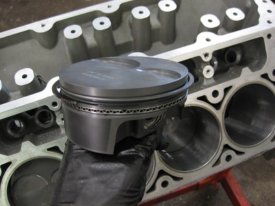
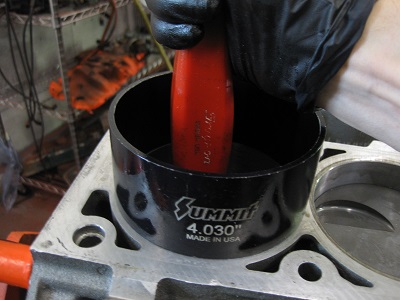
May 24, 2014 - Installing the rods and pistons was more work than I thought it would be. The first step is installing the wrist pins. They connect the rods and the pistons. The pins are easy. They slide in with a little white lithium grease. However, there are miserable little round lock rings that must be pushed inside round grooves on each side of wrist pin. These will give you fits until you figure out how to slide them in! After that, the block needed filed at the bottom of each bore so that the rod bolts would have adequate clearance and not hit the block. After cleaning up the shavings, I gapped the rings. I used a ring filer and ground the top rings to .018" and the bottom rings to .022". (Next time I'll get the pre-fit rings!) The rings were installed on the pistons and the pistons were tapped into the bore using a round ring compressor. The rod bearing clearances were checked with plasti-gauge and came out to about .0016". This is on the tight side but well within the GM spec of .0009" to .003". Finally, the rod bearings were installed with white lithium grease. This may be controversial but I've seen it used successfully hundreds of times on engine overhauls and it works just fine!
May 26, 2014 - With the 4.030" bore I was able to use L92 heads. As cast, these heads outflow any other small block head produced, rivaling some CNC-ported designs. They have a rather large port volume and a huge 2.165" intake valve which will work great on my larger-than-stock 6.7L motor. Savani Engine Machine in McKeesport performed a 3-angle valve job. I installed a set of PAC 1519 beehive valve springs, stock head gaskets, and ARP head bolts. Geoff at EPS spec'd me a custom cam designed to idle smoothly, provide big off-idle torque, and pull hard through 6,000 RPMS - just what I need for a heavy shallow-geared sleeper. To achieve this, the cam uses a healthy amount of lift, modest duration, and a wide lobe separation angle. Under the heads lies a set of Morel OE replacement lifters and stock lifter trays.
Questions, comments or suggestions about the car? Send Me Email!